
The Parts of a Hydraulic Cylinder It Still Runs Your Ultimate Older
Figure 12-2: Hydraulic system pictorial diagram. Cutaway Diagrams. Cutaway diagrams (Figure 12-3) show the internal working parts of all fluid power components in a system. The diagrams include controls and actuating mechanisms and all interconnecting piping.. Two hydraulic cylinders are attached to each JBD panel shaft by crank assemblies.

35 How To Rebuild Hydraulic Cylinder Diagram Wiring Diagram List
Hydraulic cylinder designers need to think about the scale and size of a hydraulic cylinder. A cylinder that has an excessive reach poses the risk of buckling - meaning that the rod and barrel have to be engineered to be larger. However, this increase in area would have a bigger force, potentially over engineering the fabrication and making.

The 25+ best Hydraulic cylinder ideas on Pinterest Mechanical
A hydraulic cylinder schematic diagram provides a visual representation of the different components and fluid flow paths within a hydraulic cylinder system. By studying these diagrams, engineers and technicians can gain valuable insights into the functionality and performance of hydraulic cylinders.
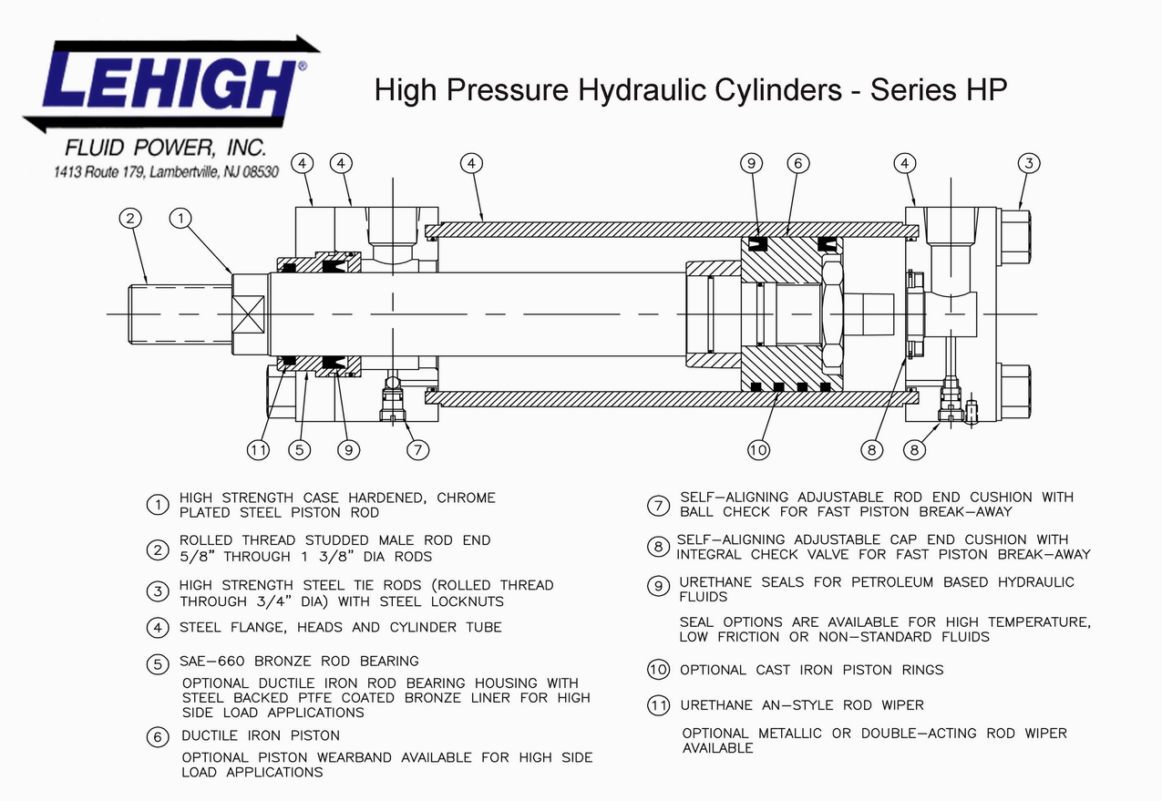
Hydraulic Cylinders Lehigh Fluid Power
Guide to Understanding Hydraulic Cylinder Parts: Names & Diagram. by Swap. A hydraulic cylinder is a mechanical actuator that gives a unidirectional motion through the force of the hydraulic liquid. It is also referred to as a linear hydraulic motor. It has a wide area of applications, ranging from the construction industry to mechanical machines.

HYDRAULIC SYSTEM FOR BEGINNERS Mechanical Engineering Professionals
Cylinders are mechanisms connected to the slide which help in moving the slide up and down. On the other side, the cylinders are mounted to the frame at the top of the system. Cylinders are one of the major components of the hydraulic system and are needed to build a hydraulic press.

If it’s an older system, it could be that the hydraulic cylinder is
A-A-52410-- Boot, dust and moisture seal: hydraulic brake cylinder, synthetic rubber. AWS D14.9/D14.9M-- Specification for welding of hydraulic cylinders. BS ISO 10100-- Hydraulic fluid power - cylinders - acceptance tests. Resources. How to Select Air Cylinders. How Hydraulic Machines Work- The Basic Idea. Image Credit: Bailey | Grainger
What Are The Parts Of A Hydraulic Cylinder? Anbao Hydraulic
Series 3H Large Bore Hydraulic Cylinders Parts Identification 52-53 Seal Kits 53 Series 3H 7" & 8" Bore Hydraulic Cylinders Parts Identification and Maintenance Instructions 54 & 55 Series HMI Cylinders Parts Identification 56-57 Seal Kits and Replacement Parts 57 Series HD-HDC Automotive Hydraulic Cylinders Service Assembly Kits 58 Seal Kits.
Machine Drawing Double acting cylinder Pneumatic Circuit
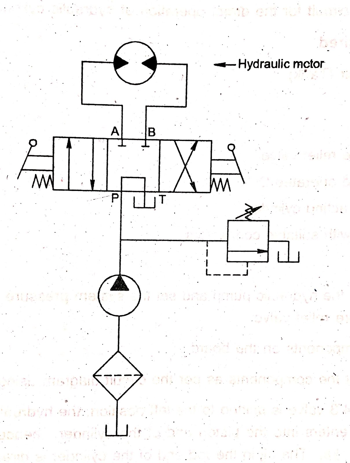
Hydraulic symbols are a standard designed to provide a clear representation of how each hydraulic component functions in a hydraulic system. Hydraulics engineers regularly encounter these diagrams, but these symbols can be daunting to interpret if you have limited experience with schematics and the fluid power industry.
Hydraulic Cylinder Hyspecs Hydraulics Australia
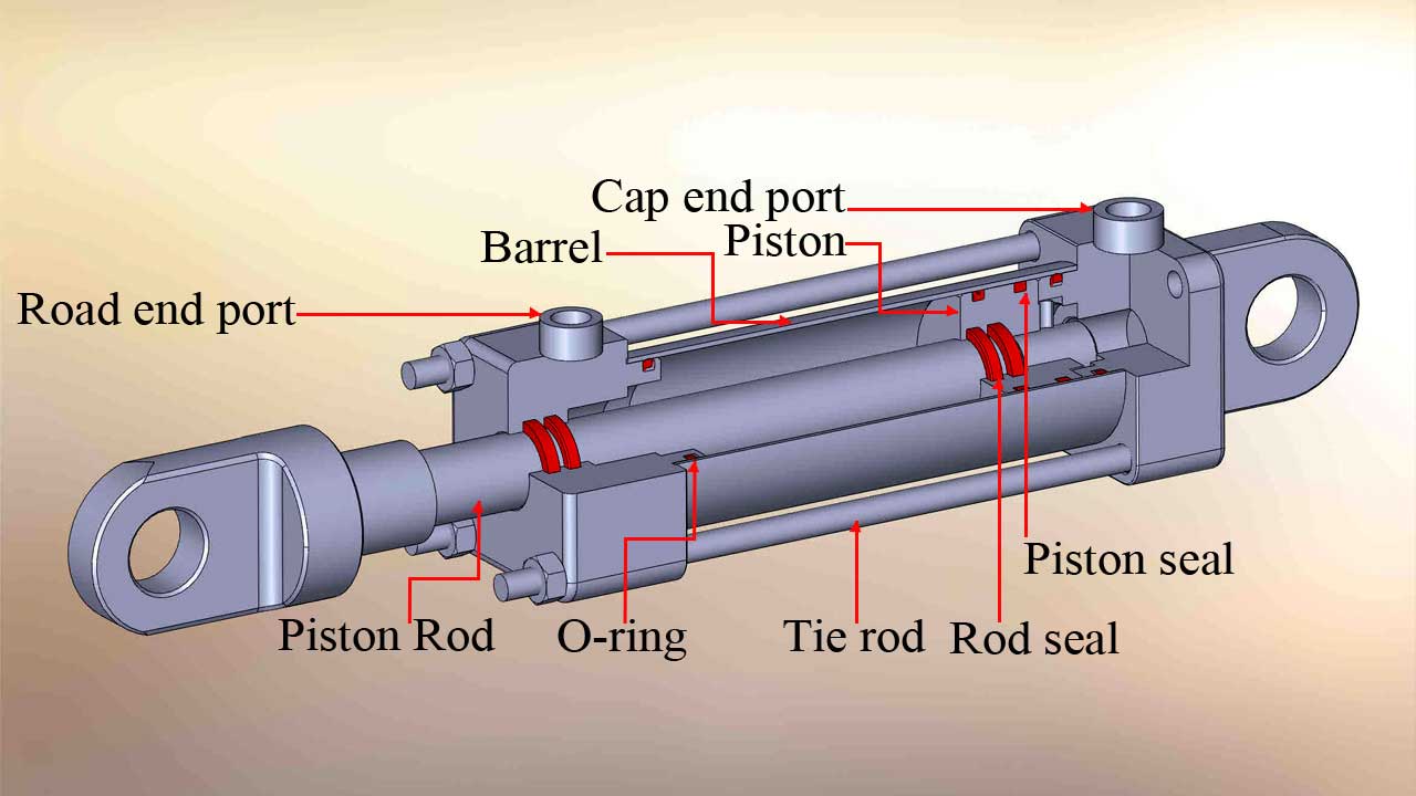
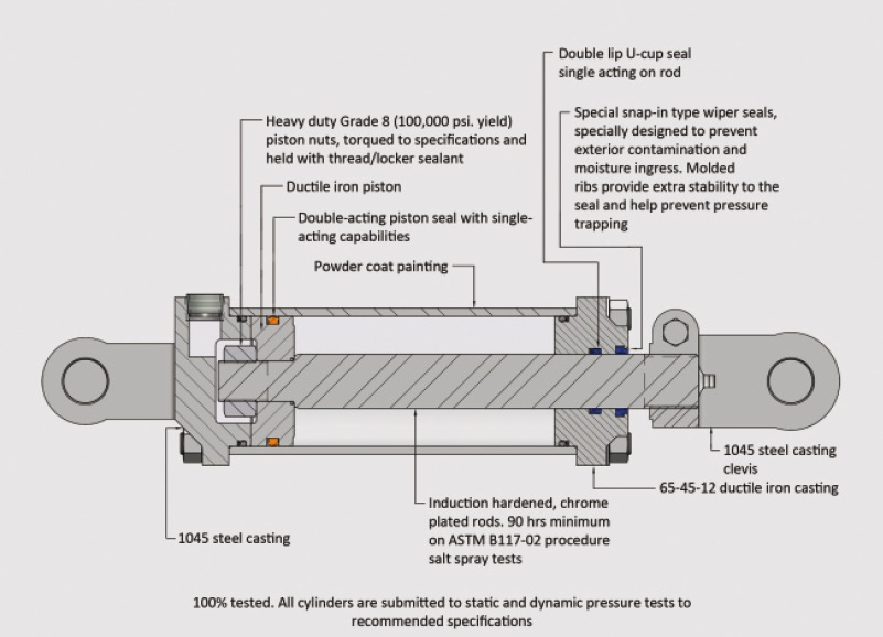
A hydraulic cylinder has eight basic components; the clevis, gland, port(s), barrel, rod, piston, the end cap, and the seal. When combined, these parts allow the hydraulic cylinder to pressurise fluid that mobilises a piston to generate power for a machine.
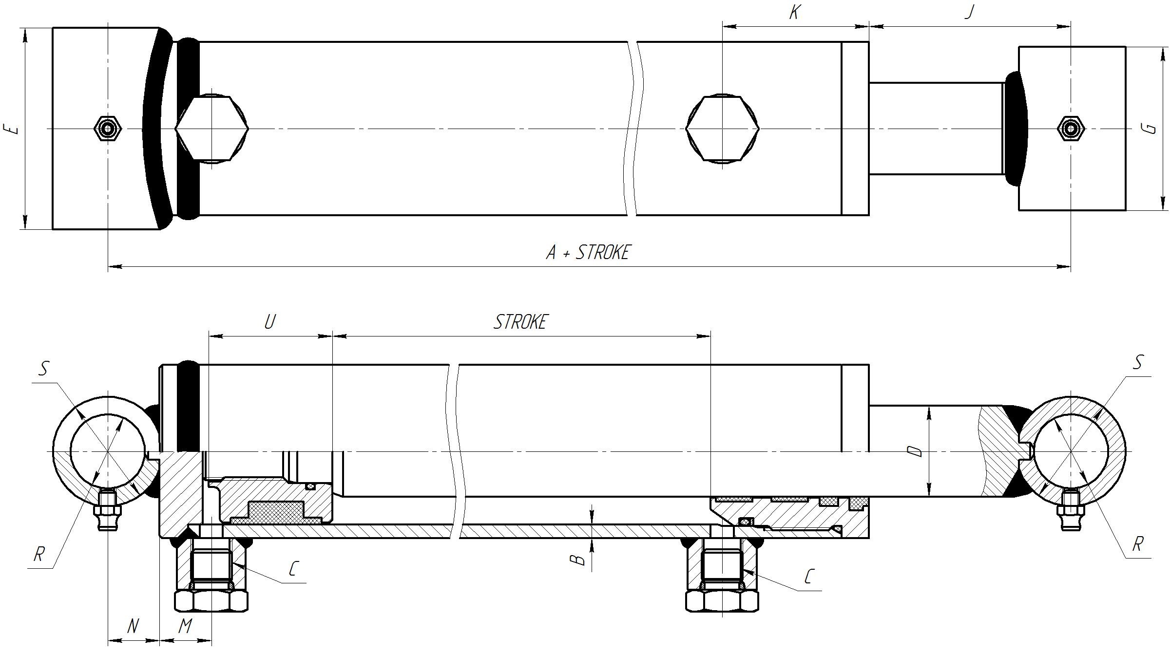
How to measure a hydraulic cylinder replacement? Magister Hydraulics
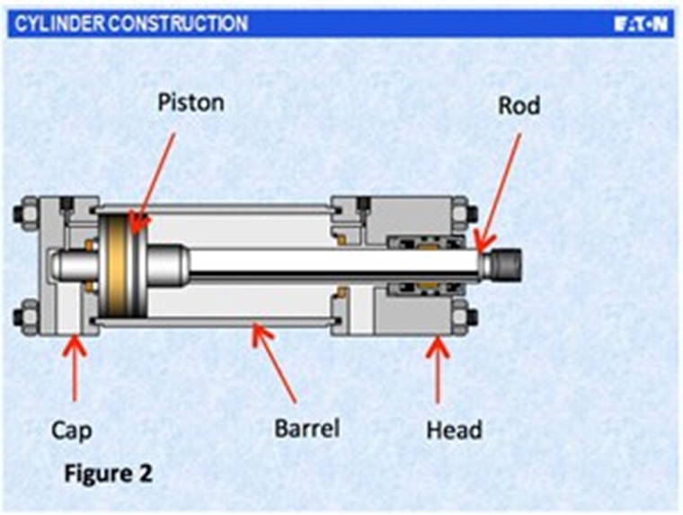
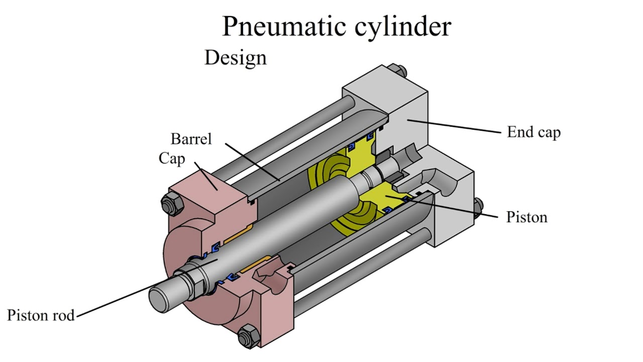
The term cylinder is commonly used to describe a device that gives linear force output and movement. A cylinder may also be referred to as a linear actuator. Cylinders are broken down into two main categories: pneu-matic and hydraulic. Pneumatic cylinders can be operated by several types of gases; however, compressed air is by far the most common.
Hydraulic Cylinder Working Principle
Hydraulic Cylinder Base/Gland. Also called the rod end, the hydraulic cylinder base is the visible opening that a cylinder rod connects to. The gland is attached with tie rods, bolts, welding, or threading. Hydraulic cylinders incorporating a tie rod utilize high-strength steel rods that are threaded for holding end caps to the barrel.
Sealing the deal in hydraulic cylinders PI Process Instrumentation
Pushing and pulling, this hydraulic cylinder diagram demonstrates the basics of a dual acting cylinder. » Click video to play/pause. What is a hydraulic cylinder? Hydraulic cylinders are a common part in a variety of machines from excavators to bulldozers to cranes, trucks, and more. While the engine, the transmission, and the tires and tracks.
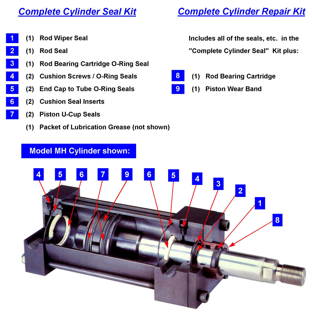
Peninsular Cylinder Co. cylinder repair, hydraulic cylinder repair
Cylinders. Cylinders are linear actuators that can produce large forces in small volumes. There are generally three types represented in a schematic. A single acting cylinder is one where hydraulic oil is only supplied to one side (usually the bore) and either gravity or springs make it return. A bottle jack is a good example of this.
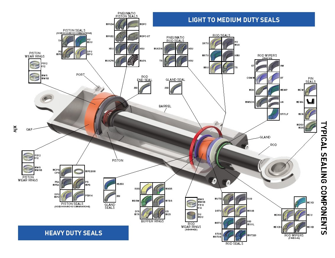
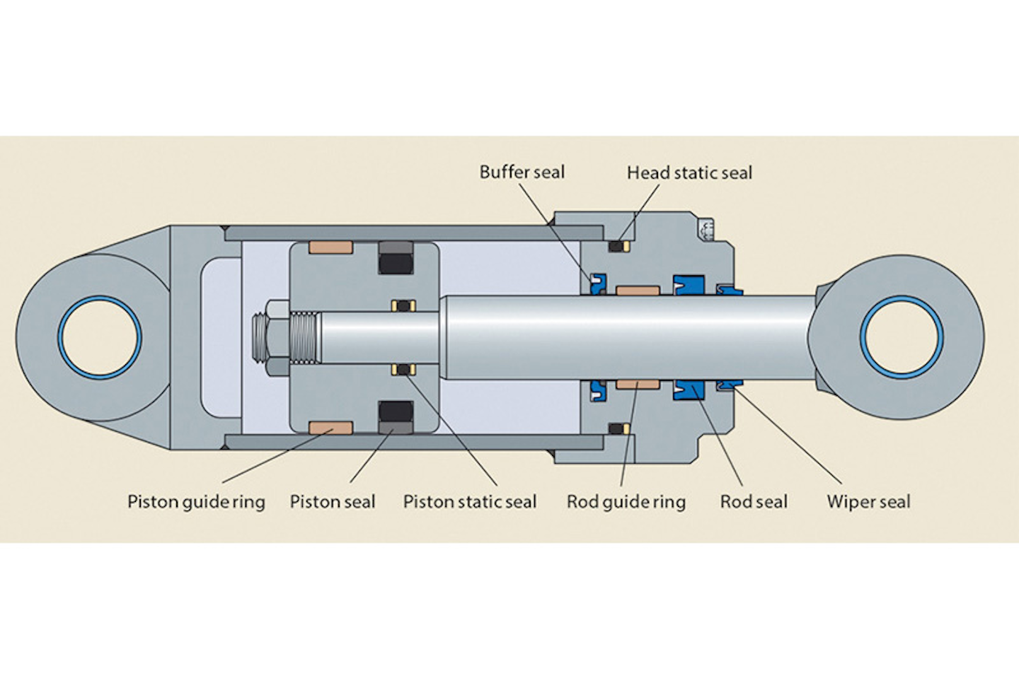
The Function of Seals In a Hydraulic Cylinder หน้าที่ของซีลในกระบอกไฮดรอลิก
How does the hydraulic cylinder work? A hydraulic cylinder has the following parts: piston, rod, seals, wipers, barrel. Read more http://www.hydraulic-calcul.

Hydraulic Cylinder Parts Diagram General Wiring Diagram
Cylinder Working a Rotating Lever: A cylinder working a hinged lever can exert its maximum force on the lever only when the lever axis and cylinder axis are at right angles. When Angle "A" is greater or less than a right angle, only part of the cylinder force is effective on the lever. The cylinder force is found by multiplying the full
Hydraulic Cylinders, Cylinder Parts and Hydraulic System Parts Supplier
Tie rod style hydraulic cylinders use high strength threaded steel rods to hold the two end caps to the cylinder barrel.This method of construction is most often seen in industrial factory applications. Small bore cylinders usually have 4 tie rods, while large bore cylinders may require as many as 16 or 20 tie rods in order to retain the end caps under the tremendous forces produced.