Star Delta Contactor Wiring Diagrams
star delta starter control circuit wiring diagram In this video, we'll show you how to do control wiring of a star delta starter, this type of starter i.

Star Delta Wiring Diagram Explained
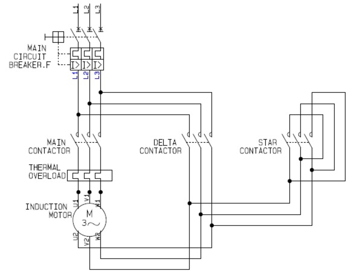
Control Circuit of Star-Delta Starter (Open Transition) Scheme - Control Circuit of Star-Delta Starter (Open Transition). Although the star delta starter wiring diagram is very helpful and easy to read. It isn't quite correct. On the delta contactor side you have W2,V2,U2 going to the motor. Which means V2 and V1, will end up being on.
Wiring Diagram Of Star Delta Connection
In a PLC-based system, the Star Delta starter using Timer operates in the following manner: Initially, the PLC reads the status of two push buttons, namely "ON" and "OFF". Once the "ON" button is pressed, "Q1" switches on and coil "K1" becomes energized, causing Timer "T1" to Start counting time. Simultaneously, when.

Star delta wiring diagram plc Up Forever
𝗛𝗼𝘄 𝘁𝗼 𝗺𝗮𝗸𝗲 𝗔𝘂𝘁𝗼 𝗦𝘁𝗮𝗿 𝗗𝗲𝗹𝘁𝗮 𝗪𝗶𝗿𝗶𝗻𝗴 𝗖𝗼𝗻𝗻𝗲𝗰𝘁𝗶𝗼𝗻 😺📺 Uncover the secrets of.

Automatic Star Delta Starter Power, Control & Wiring Diagram Electrical circuit diagram
Figure 1A: Star delta starter power and control circuits. Under normal conditions (F1, F2, and F3 are healthy), when S1 is pressed, timer coil K4 will pick up and it energizes the coil of the contactor K2, and that in turn energizes the coil of line contactor K1.. Star delta wiring diagram. Tags Motor, Switchgear, TOOLS.
Star Delta Starter Circuit (YΔ) How to Wire + Pros and Cons
A star delta starter is the most commonly used method for the starting of a 3 phase induction motor. In star delta starting an induction motor is connected i.
The Beginner's Guide to Wiring a StarDelta Circuit Factomart Singapore
The manual control procedure for the star-delta starter without timer is relatively simple. It involves the following steps: Initial State: The motor is at rest, and the windings are disconnected. Star Connection: Press the "Start" button or close the start contactor. This connects the motor windings in a star configuration.
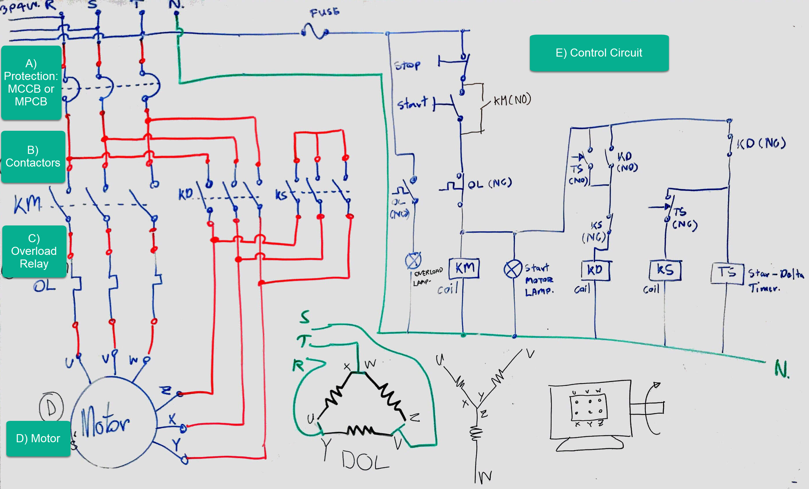
OIL AND GAS ELECTRICAL AND INSTRUMENTATION ENGINEERING STAR/DELTA STARTER CONTROL CIRCUIT
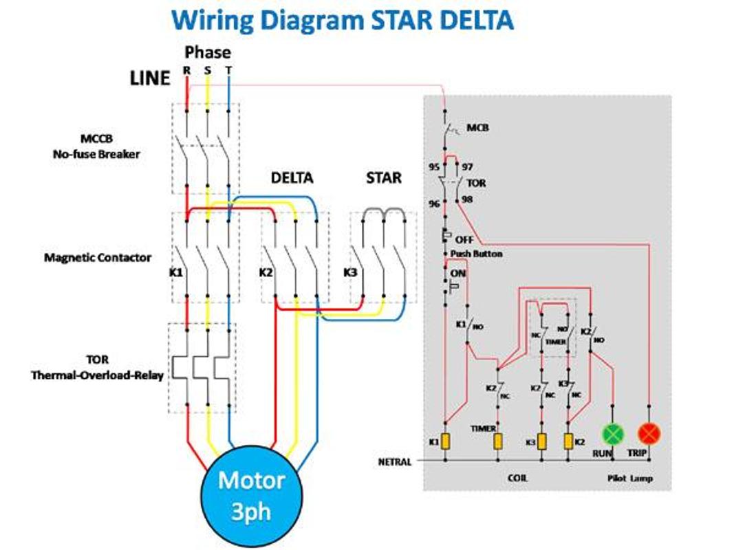
The below image represents the power and control wiring of the star-delta starter. 1. OFF Stat ⇒ This is the off stat of the starter, all the contactors are in the OFF position. 2. STAR Stat ⇒ In this stat, Main and Star contactors are closed and Delta contactor is open. The motor is connected to STAR.

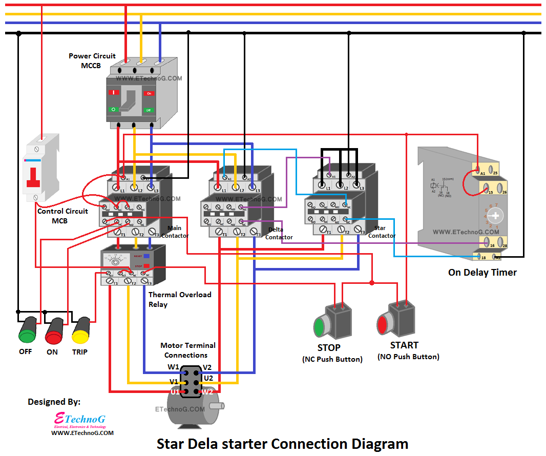
Star Delta Starter Connection Diagram and Wiring ETechnoG
Star Delta Starter commonly use in motor to lower the inrush current upon startup of the motor. A Star Delta Starter or Y Delta Connection is the most common.
Simple Star Delta Wiring Diagram Wiring Diagrams Nea
The star delta starter wiring diagram is an essential part of the electrical system in any industrial setting. It provides a safe and efficient way to control the power flow from the main power source to the motor and other components. The diagram outlines the wiring connections between the transformer, the motor, and other components, and.
Star Delta Wiring Diagram Explained
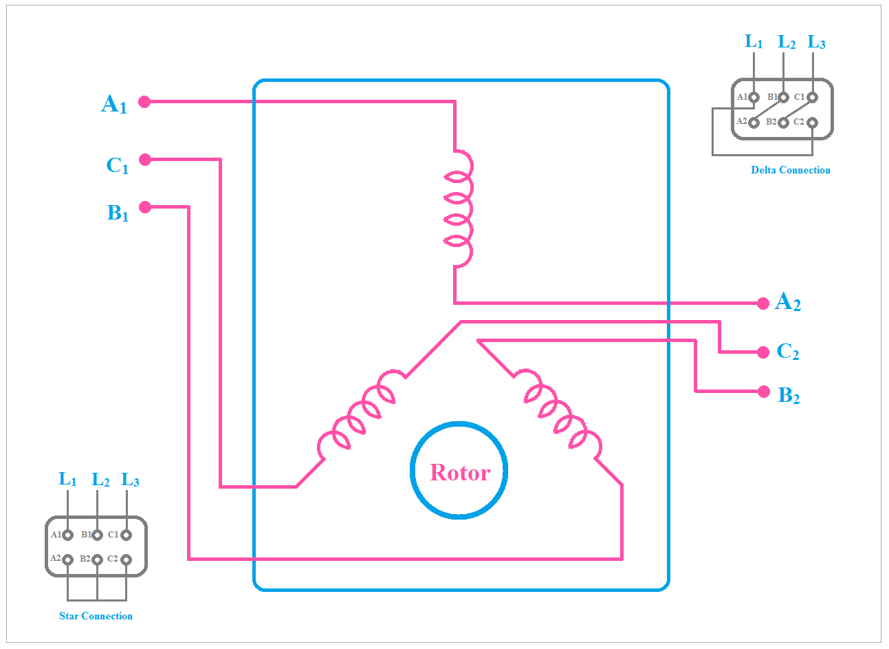
Principle of Working of Star Delta starter. The motor is first started by connecting its stator winding in a star configuration. The phase voltage in the star configuration is 1/ √ 3 of the phase-to-phase or line voltage. Thus the voltage applied to the stator winding is about 58 % of the line voltage. The starting stator current reduces to 1.
[Explained] Star Delta Starter Diagram Control and Power Circuit ETechnoG
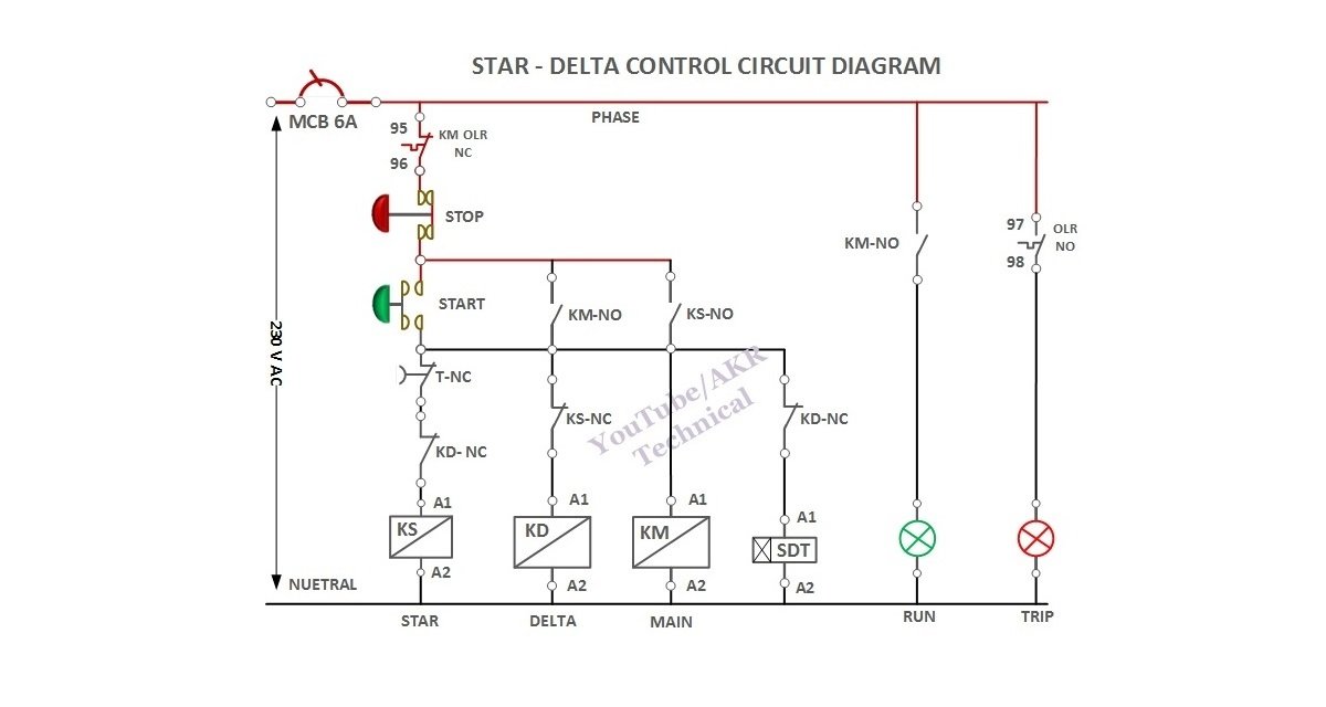
Star-Delta starter wiring diagram: Q1 serves as the main power supply switch that supplies electricity to the power circuit. The main circuit breaker Q1 connects or disconnects the main three-phase supply (L1, L2, and L3) to the motor terminals T1, T2, and T3. Fuses F1, F2, and F3 Protect the motor against overload.
Star Delta Wiring Diagram Control Circuit
star delta control wiring diagramIn this video, we will learn how to do about Star Delta Starter Control wiringThank You Arun GuptaElectricaltechnician02@gma.
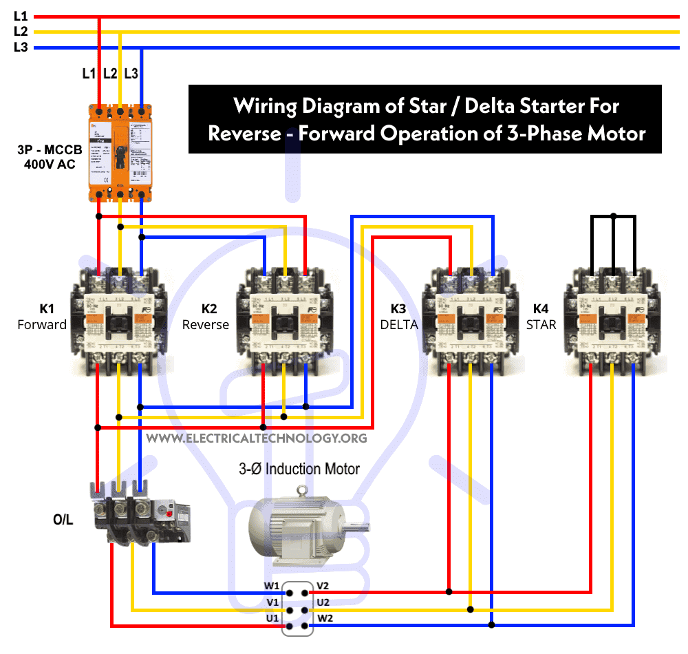
Star Delta Starter Reverse Forward Control Without Timer
Working, construction, diagram. The star-delta wiring is an electrical circuit used in the motor power control in a three-phase power supply connection. This type of wiring connection helps in reduces the initialize high voltage in the motor windings, which helps reduce the high starting current in the starting of the three-phase induction motor.
star delta starter wiring diagram
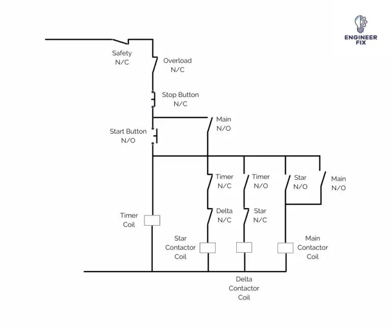
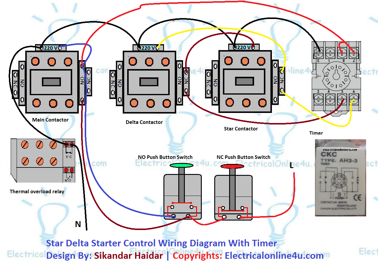
The Star Delta Starter Control Wiring Diagram With Timer is a comprehensive guide to understanding the wiring of a single-phase motor control circuit. It includes components such as a timer, a contactor, overload protection and a three-phase motor. The diagram is divided into sections - each one representing a specific component.

Star Delta Wiring Diagram 3 Phase
Below are two examples of wiring diagrams for star delta starters from industry suppliers. By the end of this tutorial you will understand how these work.. To control the changeover from star to delta contactors we simply use a timer to control this. It will automatically change the configuration over after a set amount of time. Additionally.