
HowMechanismWorks ? What are Gear Pumps? How Do They Work?
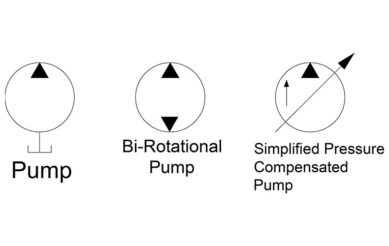
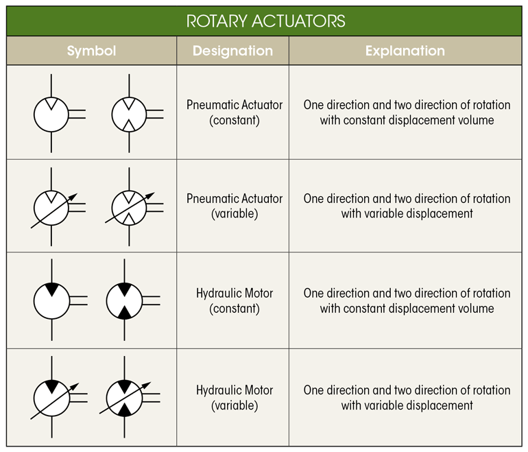
The dark upper triangle in these hydraulic symbols indicates fluid going out of the system and hence represents a pump. In the case of the hydraulic motor, the dark triangle is inverted indicating that the fluid is entering into the system. A hydraulic motor converts hydraulic energy into mechanical energy.
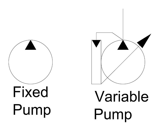
What is the difference between fixed and variable pumps?
Piping and Instrument Diagram Standard Symbols Detailed Documentation provides a standard set of shapes & symbols for documenting P&ID and PFD, including standard shapes of instrument, valves, pump, heating exchanges, mixers, crushers, vessels, compressors, filters, motors and connecting shapes. Or Gate Not Gate Correcting Element Diamond
Centrifugal pump symbol icon Royalty Free Vector Image
Instrument PID Symbol: Mechanical PID Symbol: Pump PID Symbol: Compressor PID Symbol: Pipe PID Symbol: HEAT Exchanger PID Symbol: Function PID Symbol: Actuator PID Symbol: Positioner PID Symbol:
Hydraulic Electric Motor Symbol, 1 Hydraulic components symbols use
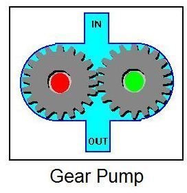
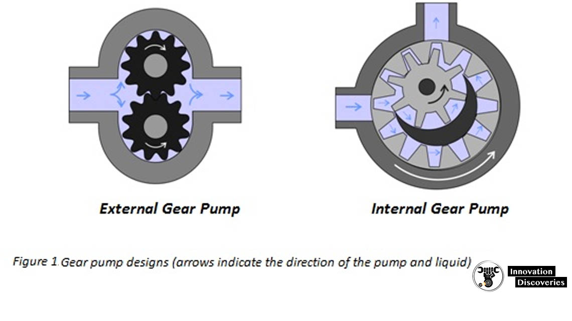
Lesson 1: Gear Pump Basics Division of McNally Industries Northern Pump manufactures gear pumps that are positive displacement, rotary pumps, with two gears of equal size. The drive shaft and gear is rotated by a motor or by extension of a auxiliary motion shaft. The drive gear turns the driven shaft and gear. Drive Shaft

Mechanical Drawing Symbols Process Flow Diagram Symbols Design
P&ID symbols exist for show major components and lines, such as valves, vessels, instruments, pumps, compressors, the towers. And ISA S5.1, ISO 10628, and BT 5070 cover this standardization by P&ID symbols also guide process engineers in ihr plant design activities.

P & ID y PFD Drawing Symbols and Legend list (PFS & PEFS) Chad Wilken's
GD5 gear pump is a floating bushing, pressure balanced design with a high strength extruded aluminum body, cast iron end cover and cast iron mounting flange. The wide choice of shafts, flanges and ports in compliance with all international standards (SAE, DIN, ISO and European). Displacements from 5.1cm³/rev (0.31in³/rev) to 24.0 cm³/rev (1..
How To Read P&ID , Basic And Advanced Knowledge?
Gear Pump 101 Lesson 2: Gear Pump Terminology When your reputation depends on it! Discharge Pressure Discharge pressure = Gauge pressure the pump must produce to force the liquid out of the pump and into the system piping, and overcome the potential combination of: All pressure loss in pipe from elbows, valves, filters, connections etc.

P&ID and PFD Drawing Symbols and Legend list (PFS & PEFS) Piping and
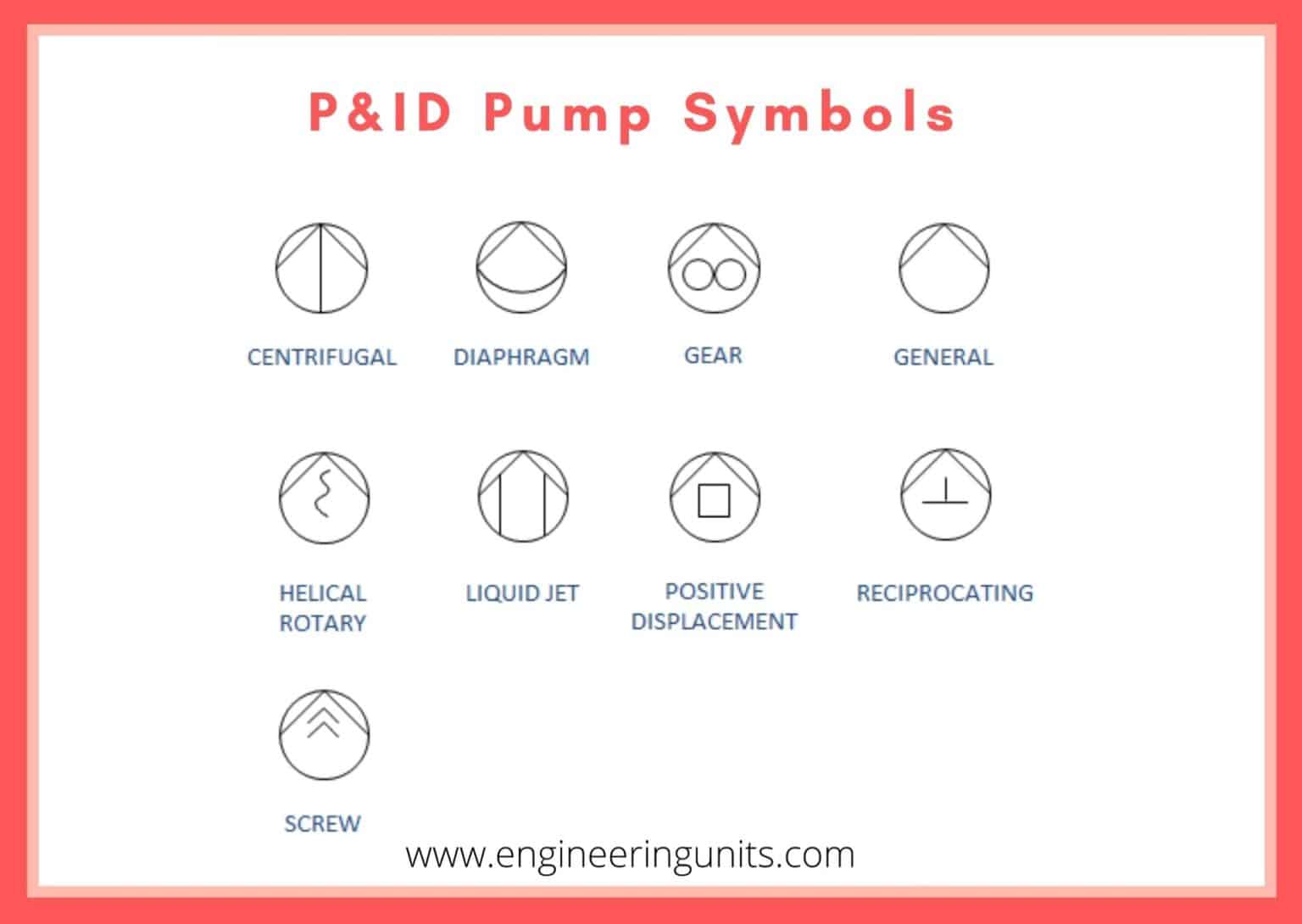
The most common P&ID symbols are listed below: lines piping components (pipes, flanges, and fittings) valves filters instruments and instrumentation pumps compressors vessels electrical machines (motors, generators, and turbines) heat exchangers LINES P&ID SYMBOLS PIPING P&ID SYMBOLS VALVES P&ID SYMBOLS FILTERS P&ID SYMBOLS INSTRUMENTS P&ID SYMBOLS

Gear Pump Gear Pump Symbol P&id
The symbols for a gear pump, a vane pump, a piston pump or any other type of physical configuration does not carry with it any symbolic difference, nor does it matter as you'll find out by the end of this.
Differences Between the Centrifugal Pump and Positive Displacement Pump
Centrifugal Ticker 01 symbol. Centrifugal Pumps 02 symbol. Radial Pumps 03 P&ID symbol. Centrifugally Pumps 04 P&ID badge. Centrifugal Pumps 05. ISO Centrifugal Pump symbol. ISO Diaphragm Pump symbol. ISOLATE Positive Displacement Pump symbol. Liquidity Ring Vacuum Pump mark.

P&ID and PFD Drawing Symbols and Legend list (PFS & PEFS)
Symbols ∆. Lesson 2: Gear Pumping Terms. The rate of flow of a gear pump is the quantity of fluid actually delivered per unit of time, including both the liquid and any dissolved or entrained gases, at stated operating conditions. In the absence of any vapor entering or forming within the pump, rate of flow is equal
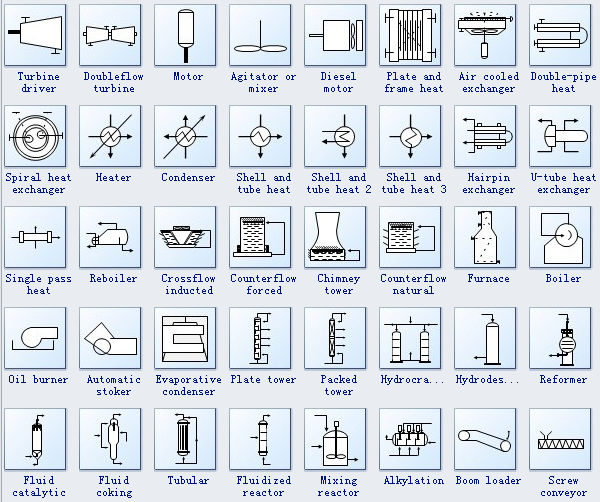
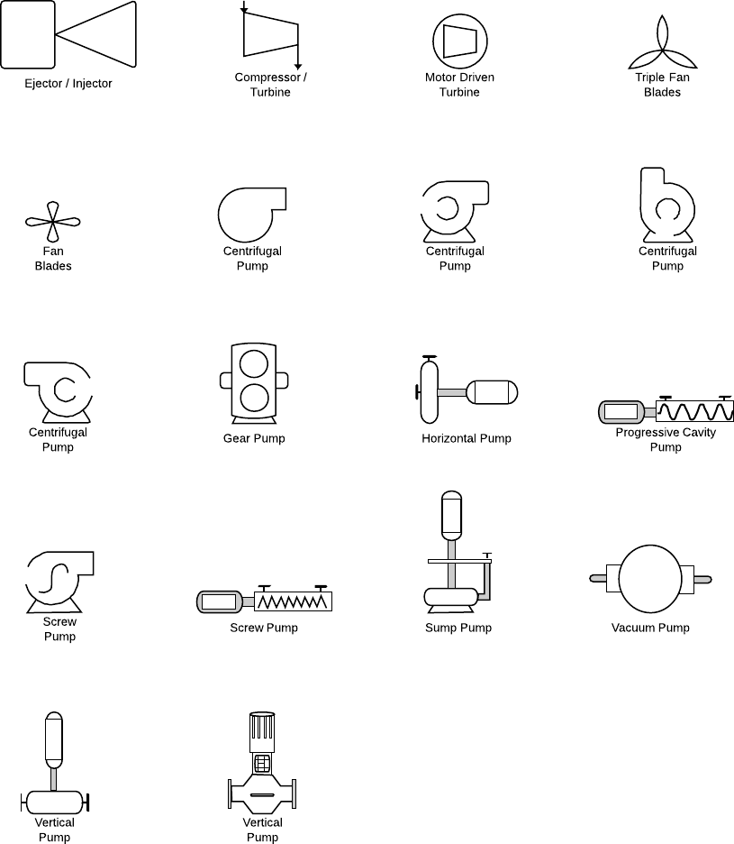
Process and Instrument Diagram Symbols
Pre-drawn process and instrument diagram symbols like centrifugal pump, vertical pump, screw pump, bin and more help create accurate diagrams and documentation. Download. Pricing. Gear pump uses the meshing of gears to pump fluid by displacement. Motor is a device that creates motion. It usually refers to an engine of some kind.
Useful information on Gear Pumps
Gear and vane pumps come in a wide variety of configurations. Figures 15-1 through 15-3 show one or more pumps in a single housing. The pumps may share a common inlet or have multiple inlets.. Symbol for High-low pump Fixed-displacement pump circuits Figure 15-6 shows a schematic circuit for a fixed-displacement pump operating a single.
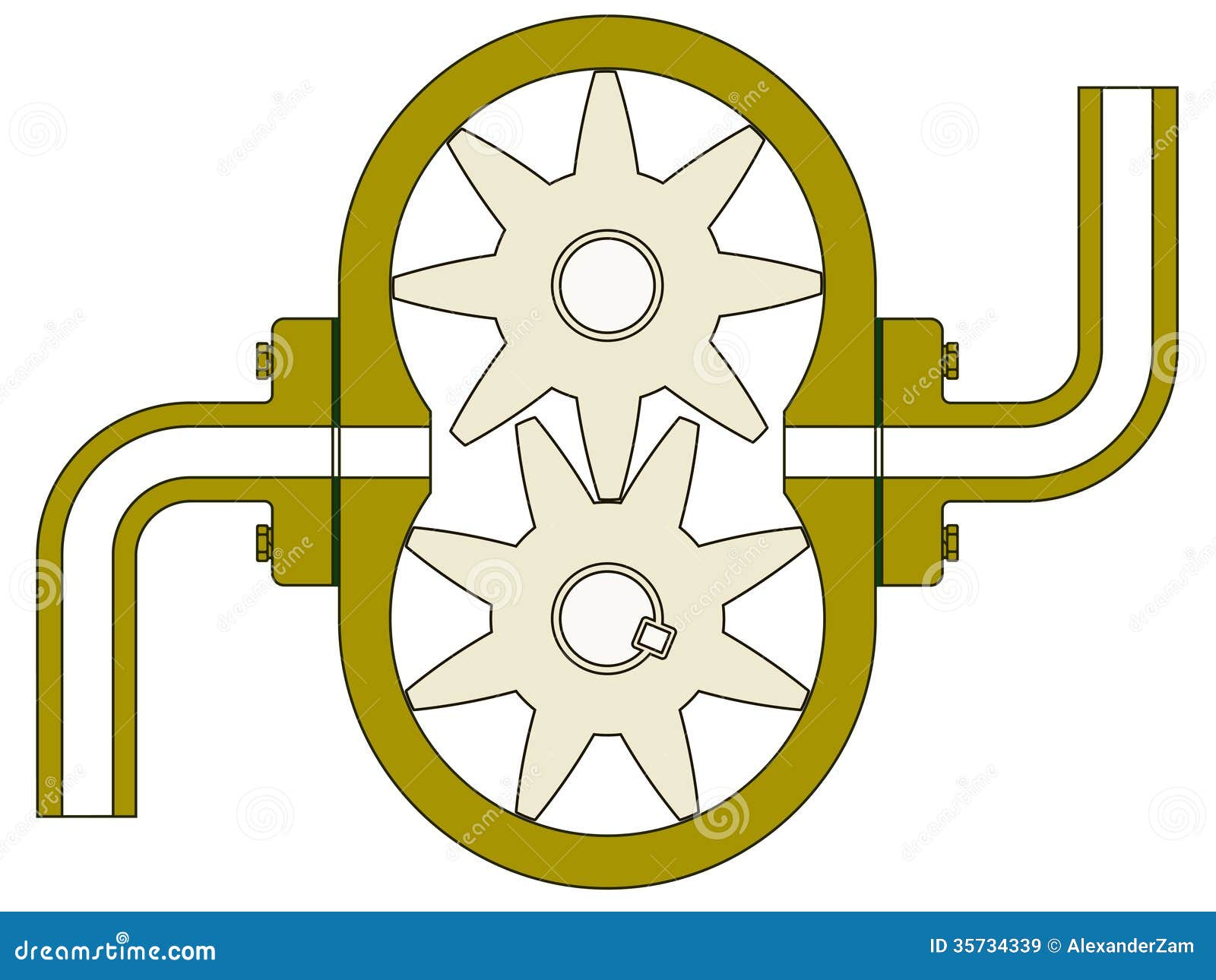
Gear pump stock vector. Illustration of airengine, machine 35734339
Positive Displacement Pump 02 symbol: Positive Displacement Air 03 symbol: Proportionating Pump symbol: Pump 01 key: Reciprocating Pump 01 symbol: Reciprocating Pump 02 symbol: Rotary Gear Pump symbol: Rotary Pump symbol: Screw Pump 01 symbol: Screw Pump 02 symbol: Immersible Pump symbol: Sump Pump graphic: Turbine Pump icon: Vacancy Pump.
Symbole und Notation von R&Ischema Lucidchart
Mechanical Engineering solution — 8 libraries are available with 602 commonly used mechanical drawing symbols in Mechanical Engineering Solution, including libraries called Bearings with 59 elements of roller and ball bearings, shafts, gears, hooks, springs, spindles and keys; Dimensioning and Tolerancing with 45 elements; Fluid Power Equipment.
Hydraulic Schematic Diagram Symbols
This symbol represents a pump, a device that is used to move fluids, such as liquids or gases, from one place to another. Pump schematic symbols are used in various engineering fields, including mechanical, electrical, and hydraulic systems.